Computational Fluid Dynamics
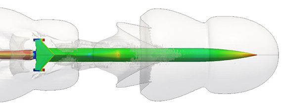
CFD software gives us the power to simulate flows of gases, liquids, heat and mass transfer through computer modelling. Using CFD software, we can build a ‘virtual prototype’ of Aussie Invader 5R and then apply real-world physics to the model, and the software will provide us with images and data, which predict the performance of that design. This was used early on in the design of Aussie Invader 5R. The actual car you see today was built the way it is from what we determined early on in our quest to build the World’s most powerful car.
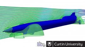
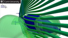
The Aussie Invader team has assembled a crack team of Mechanical Engineers from Curtin Universities Fluid Dynamics Research Group (FDRG) and iVec to assist us with some of the major hotspot areas on our car, that need some serious design and CFD calculations input.
Certain features of our car have been set in stone from the time of her inception, for example, centre of gravity, centre of area, frontal area profile, windscreen angle and location for rocket motor hardware and plumbing. Other areas of our car’s design where dependent on the CFD work, such as, nose cone, front wheel fairing, vertical and horizontal stabilisers. Other considerations this threw up were, the deflected ground-effect shock wave from “V” shaped underbelly, canard and rear axle fairing options. These were unknowns in the early days, but the CFD work that was carried out have meant these were produced with the best knowledge and information available.
CFD For The Nose Design
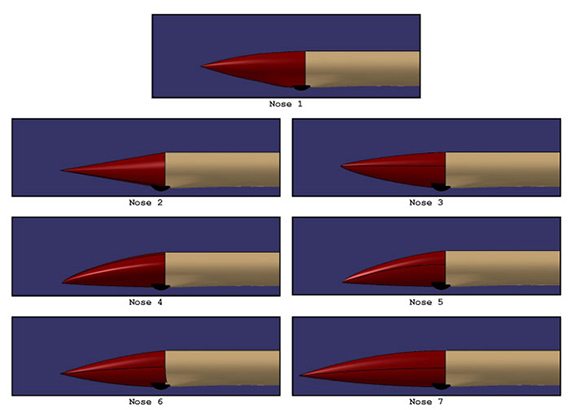
Dan McKeon was an early member of the Aussie Invader team. He was tasked with running the program to assess different nose designs for Aussie Invader 5R. The nose design is one of the most critical parts of the car, as it sets up the airflow over the whole car, and getting the nose design wrong could mean the car could be very unstable and dangerous.
Dan ran many tests on several different nose designs and the CFD results helped in the final selection of the nose design. The program determined that a nose angle of one degree down was the best overall design for our needs.
The car will experience many challenges as the speed and aerodynamics change through its speed ranges. We are confident we have got it right as Dan is one of the best CFD gurus, having been a Formula One aerodynamicist and a ballistics expert.
Pressure Contour
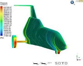
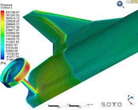
Early development of Aussie Invader 5R’s CFD was also undertaken by Soto Engineering and these images are courtesy of them and the work they initially undertook. The following selection of early CFD images has helped us to develop Aussie Invader 5R and refine many aspects of the initial design. The images on the left show a pressure plot through the length of the model, showing relatively high pressure acting upon the nose, front wheels and bottom and rear end of the car.
Mach Numbers
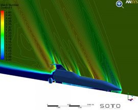
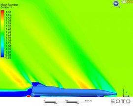
These images depict the changing Mach number generated by the shape of the car. The contour lines illustrate where the Mach number is changing in relation to the fluids’ velocity. As can be seen, there is a build-up around the front and rear wheels. These areas show where strong shocks will form when the vehicle goes supersonic.
Velocity
The following images depict the velocity of the fluid stream around the vehicle. As can be seen, there is a high velocity produced by protruding geometries such as wheels and air foils. The rear of the vehicle produces a considerable wake as does the rear wheels. Areas in red show where the fluid stream is moving quickly and thus creating pressure drag on the vehicles surfaces.
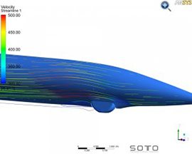
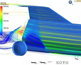
These images are from work conducted in the early stages to allow us to understand the areas of car that needed our attention. We will never be able to make this car completely aerodynamic. Our main goal is to reduce the drag as much as possible and try to make Aussie Invader 5R as safe and predictable as we can. No car car ever operated in such a hostile and constantly changing environment.
