The Design and Configuration
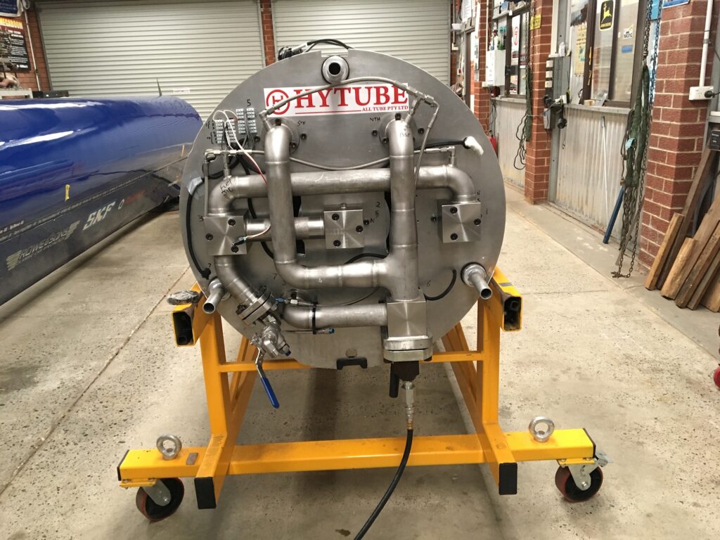
Our OPM has a pressure rating of 1000 psi and comprises a module of 7 x 6m long tubes, four are for the oxidiser and three are for the fuel. These tubes are all fitted with pistons with a ring magnet mounted under the piston crown. An inert high pressure gas, Gaseous Nitrogen (GN2) acts against the pistons forcing the propellants into the rocket engines injector where the meet and create a hypergolic reaction (chemical ignition).
One of the big jobs in building this all Aussie propellant delivery system was in the electronic piston logging location needed to monitor our engines performance and our shifting centre of gravity, along with several other important details. The AT&M electronic strips with LED lights can be seen showing piston travel down the length of of the tanks. The video above is of an initial low pressure system test, using a 100 psi.
Propellant Distribution Manifold

This is the back end of the tank, and where the Gaseous Nitrogen (GN2) is forced into the OPM. This force acting on the pistons, pushes the propellants into the engine. The force on the pistons can be varied from 450 psi to 750 psi via regulators. The higher the pressure, the more power the engine produces.
Piston & Logging Magnets

These are the internal pistons with ring magnets and retaining plates. There are also a set of highly specialised seals (not shown in the image above) that fit in the piston ring grooves and seal the pistons to the tank walls. It is critical for safety that no propellant leaks past the seals in this high pressure environment.
Blow-down Inlet Manifold

This is the Distribution Manifold that takes the propellants from the tanks via a set of tubes to the rocket engine. The propellants are White Fuming Nitric Acid (WFNA – Oxidiser) and Turpentine (Fuel). These mix in the engine and ignite, producing around 62,000 lb/f (equivalent to about 200,000 hp).